Home › Unlabelled ›
Relay Panel Wiring Diagram / Wiring Diagram Of Switches And Relays To The Plc Download Scientific Diagram - As shown, the power source is given to the electromagnet through a control switch and.
Relay Panel Wiring Diagram / Wiring Diagram Of Switches And Relays To The Plc Download Scientific Diagram - As shown, the power source is given to the electromagnet through a control switch and.. Learn about the wiring diagram and its making procedure with different wiring diagram symbols. The following diagram shows a typical field wiring example. A wiring diagram is a simplified conventional pictorial representation of an electrical circuit. Provides circuit diagrams showing the circuit connections. A relay is an electrically operated switch.
Business > industrial devices > automation controls top > components & devices > relays / couplers > photomos > photomos schematic and wiring diagrams. Runs scheduled and photocell events autonomously. Relays in each lmcp panel can be assigned to up to 99 automation groups in any combination. The switch may have any number of contacts in multiple contact forms, such as make contacts, break contacts, or combinations thereof. A wiring diagram is a simplified conventional pictorial representation of an electrical circuit.
2012 Volvo S60 Navigation Fuses Diagram Best Wiring Diagrams Dome Asset Dome Asset Ekoegur Es from i0.wp.com Each page of this wiring diagram shows the exact wiring for different sections of this control panel. The wiring diagrams are grouped into individual sections. It consists of a set of input terminals for a single or multiple control signals, and a set of operating contact terminals. The switch may have any number of contacts in multiple contact forms, such as make contacts, break contacts, or combinations thereof. As relay diagrams show, when a relay contact is normally open (no), there is an open contact when the relay is not energized. An iron core is surrounded by a control coil. As shown, the power source is given to the electromagnet through a control switch and. (in1 and in2) or l12 with monitored manual reset.
Mgi's most flexible modular relay panel is designed for easy installation.
Simply select a wiring diagram template that is most similar to your wiring. This includes ac schematics and dc schematics and diagrams that prominently feature relaying. How t o read the wiring diagrams contents of wiring diagrams. The components location, wiring, and termination in the interposing relay panel (irp) shall be as per the approved system drawing. Misuse can result in serious injuries. Runs scheduled and photocell events autonomously. The diagram shows an inner section diagram of a relay. Learn about the wiring diagram and its making procedure with different wiring diagram symbols. Create wiring diagrams, house wiring diagrams, electrical wiring diagrams, schematics, and more with smartdraw. The article also contains the purpose and benefits of creating a type of wiring diagram wiring diagram vs schematic diagram how to read a wiring diagram: It is also possible for a sticking component or relay to cause a. Business > industrial devices > automation controls top > components & devices > relays / couplers > photomos > photomos schematic and wiring diagrams. If you're not familiar with mains voltage ask someone who is to help you out.
Wiring diagram a wiring diagram shows, as closely as possible, the actual location of all component parts of the device. The wiring diagrams are grouped into individual sections. Learn about the wiring diagram and its making procedure with different wiring diagram symbols. A relay is an electrically operated switch. As relay diagrams show, when a relay contact is normally open (no), there is an open contact when the relay is not energized.
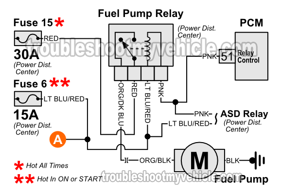
Jeep Relay Wiring Wiring Diagram System Clue Norm A Clue Norm A Ediliadesign It from troubleshootmyvehicle.com The remainder of this chapter dedicates two to three pages to each of the eight versions of dl105 micro plcs. Understanding relays & wiring diagrams what is a relay and how does it work? As shown, the power source is given to the electromagnet through a control switch and. Business > industrial devices > automation controls top > components & devices > relays / couplers > photomos > photomos schematic and wiring diagrams. Local network a or b. Connector 3c connects the instrument panel wire and j/b no.3. Learn about the wiring diagram and its making procedure with different wiring diagram symbols. Single pole single throw (spst) relay wiring diagram.
Two wires are tagged as 1 and two wires are tagged as 2.
The diagram shows an inner section diagram of a relay. Important the safety mat wiring must be. J/c (1) instrument panel wiring harness and body wiring harness combination stop lamp switch diagnosis connector engine control relay fuel pump relay space connector (radio) front door wiring harness. As relay diagrams show, when a relay contact is normally open (no), there is an open contact when the relay is not energized. The central/ relay panel includes common power circuits, such as battery power (30), ignition switched power (15), load reduction (75/x), and ground (31). Use relay location and electrical wiring routing sections to find each part, junction block and wiring harness example : A wiring diagram is a simplified conventional pictorial representation of an electrical circuit. The components location, wiring, and termination in the interposing relay panel (irp) shall be as per the approved system drawing. It consists of a set of input terminals for a single or multiple control signals, and a set of operating contact terminals. (in1 and in2) or l12 with monitored manual reset. In this example, we're dealing with mains voltage. It is also possible for a sticking component or relay to cause a. Simply select a wiring diagram template that is most similar to your wiring.
The wiring diagrams below serve to show each pin of the relay and what they each represent, so a user can know how to wire them up when connecting them. This includes ac schematics and dc schematics and diagrams that prominently feature relaying. The remainder of this chapter dedicates two to three pages to each of the eight versions of dl105 micro plcs. The wiring diagrams are grouped into individual sections. The following diagram shows a typical field wiring example.
5 Pin Relay And Socket Harness Mgi Speedware from mgispeedware.com What's the difference between 4 or. J/c (1) instrument panel wiring harness and body wiring harness combination stop lamp switch diagnosis connector engine control relay fuel pump relay space connector (radio) front door wiring harness. It is also possible for a sticking component or relay to cause a. The coil of wire causes an electromagnetic field. Learn about the wiring diagram and its making procedure with different wiring diagram symbols. As shown, the power source is given to the electromagnet through a control switch and. Business > industrial devices > automation controls top > components & devices > relays / couplers > photomos > photomos schematic and wiring diagrams. Single pole single throw (spst) relay wiring diagram.
In this example, we're dealing with mains voltage.
Proudly built in north america. It is described on page 22 of this. An iron core is surrounded by a control coil. Based on the diagram, one of these wires with the tag 2 goes to the plc digital input. Local network a or b. The wiring diagrams are grouped into individual sections. The armature opens and closes the contacts. The article also contains the purpose and benefits of creating a type of wiring diagram wiring diagram vs schematic diagram how to read a wiring diagram: It shows the components of the circuit as simplified shapes, and the power and signal connections between the devices. The components location, wiring, and termination in the interposing relay panel (irp) shall be as per the approved system drawing. The switch may have any number of contacts in multiple contact forms, such as make contacts, break contacts, or combinations thereof. Misuse can result in serious injuries. Smallest size (10.2 × 18.2 × 14.8 mm) at 10a switching capacity relay for high density p.c.