Aem Wideband Wiring Diagram / Aem 35 8460 Wiring Diagram / The serial cable also needs a chassis ground.. Type of wiring diagram wiring diagram vs schematic diagram how to read a wiring diagram: To bridge these i followed the method (just the method use the wires and resistors i tell you) of this gentleman. Deadtime is the delay between when exhaust gas composition changes and when that change is reported by the o2 sensor. I crimped a terminal onto the white wire from the gauge that will go to pin c16 so i don't have to cut the factory wire and solder the aem wire into it. Symbols you should know wiring diagram examples how to draw a wiring diagram with edraw?
Configure the wideband input source by selecting which ever input source you plan on wiring your he also shows you how to set up related searches for aem x series wideband wiring diagram aem wideband wiring diagramaem x series wideband. The first diagram is the wiring. You'll want to use red, black, and white. Below are links to the parts i installed. Connect the flying lead wires as shown in figure 1.
Stumped... Looking for ideas - RX7Club.com from www.rx7club.com Afr afr gasoline afr upper limit afr gasoline afr lower limit afr gasoline manifold pressure psi engine speed rpm 4. Aem wideband failsafe gauge name. You have to plug the sensor into an extra o2 bung, which plugs into the guage. The days of you unscrewing a couple of spark plugs to track your engine's air/fuel ratios are long gone. The first diagram is the wiring. Type of wiring diagram wiring diagram vs schematic diagram how to read a wiring diagram: This serial cable which has. Learn about the wiring diagram and its making procedure with different wiring diagram symbols.
Insert the aemnet+ terminal (white wire) into the available pin 13 on the wideband failsafe connector.
Configure the wideband input source by selecting which ever input source you plan on wiring your he also shows you how to set up related searches for aem x series wideband wiring diagram aem wideband wiring diagramaem x series wideband. I need to know what wire (color) i need to tap into for the power source when hooking up the aem air/fuel wideband. Simple wiring and installation, the controller is. The sensor contains an integrated heating element and will since aem is unable to. Aem wideband failsafe gauge name. Hmm anybody have any pictures of there setup? Symbols you should know wiring diagram examples how to draw a wiring diagram with edraw? The days of you unscrewing a couple of spark plugs to track your engine's air/fuel ratios are long gone. Type of wiring diagram wiring diagram vs schematic diagram how to read a wiring diagram: Use wiring diagrams to assist in building or manufacturing the circuit or electronic device. They are also useful for making repairs. Installation instructions, setup info and wiring diagram for aem wideband oxygen sensor. To bridge these i followed the method (just the method use the wires and resistors i tell you) of this gentleman.
Even the menu is self explanatory without needing to refer to the instruction manual each time you. I need to know what wire (color) i need to tap into for the power source when hooking up the aem air/fuel wideband. Each part ought to be placed and connected with other parts in particular manner. I just got a wideband, and was wondering where you guys where getting ur 12v 10a source from and where you routed the white wire. A white and brown wire comes off the main wideband harness.
Aem Wideband Wiring Diagram | Manual E-Books - Aem ... from annawiringdiagram.com Insert the aemnet+ terminal (white wire) into the available pin 13 on the wideband failsafe connector. Use wiring diagrams to assist in building or manufacturing the circuit or electronic device. I'm assuming this is the aem uego wideband. Installation instructions, setup info and wiring diagram for aem wideband oxygen sensor. I just got a wideband, and was wondering where you guys where getting ur 12v 10a source from and where you routed the white wire. You have to plug the sensor into an extra o2 bung, which plugs into the guage. Important notes on wideband sensors, gauge installation. Hmm anybody have any pictures of there setup?
The serial cable also needs a chassis ground.
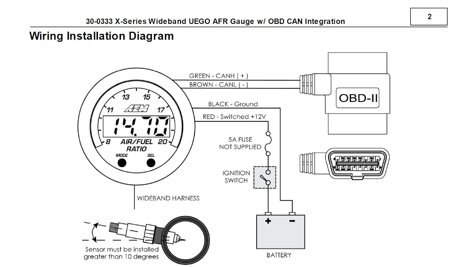
A white and brown wire comes off the main wideband harness. Important notes on wideband sensors, gauge installation. Use wiring diagrams to assist in building or manufacturing the circuit or electronic device. You have to plug the sensor into an extra o2 bung, which plugs into the guage. Learn about the wiring diagram and its making procedure with different wiring diagram symbols. The simple basic 2 wire connection makes portability of this gauge across multiple vehicles a breeze. I just got a wideband, and was wondering where you guys where getting ur 12v 10a source from and where you routed the white wire. Hmm anybody have any pictures of there setup? Connect the flying lead wires as shown in figure 1. Plug the uego sensor connector on the uego controller into the mating. Afr afr gasoline afr upper limit afr gasoline afr lower limit afr gasoline manifold pressure psi engine speed rpm 4. You'll want to use red, black, and white. Customize hundreds of electrical symbols and quickly drop them into your wiring diagram.
I just got a wideband, and was wondering where you guys where getting ur 12v 10a source from and where you routed the white wire. I will be wiring my wideband aem gauge into my aem v2 ecu soon. The wire will come through behind the glovebox area. Is there a wire i can tap into under the steering column? I crimped a terminal onto the white wire from the gauge that will go to pin c16 so i don't have to cut the factory wire and solder the aem wire into it.
Aem Wideband Wiring Diagram from phearable.net The aem inline wideband uego gives all the benefits of the aem wideband air/fuel gauges to those who do not require or want an additional perfect for data logging, engine management systems or racing applications where a gauge is not desired. Mount the uego sensor as shown in figure 2. Ive had some issues wiring my aem uego wideband gauge to my link g4plus ecu, ive ran the white 5v analog + wire and connected it to my original the wideband gauge reads normal lambda, a bit rich at idle 0.9 on e85 but on pc link after configuring the calibration my lambda 1 reads completely wrong. I will be wiring my wideband aem gauge into my aem v2 ecu soon. I have the same aem wideband (currently not installed) but im going to run it separate from the oem o2 sensor. Even the menu is self explanatory without needing to refer to the instruction manual each time you. Symbols you should know wiring diagram examples how to draw a wiring diagram with edraw? The sensor contains an integrated heating element and will since aem is unable to.
A white and brown wire comes off the main wideband harness.
The wire will come through behind the glovebox area. April 28, 2019april 27, 2019. I just got a wideband, and was wondering where you guys where getting ur 12v 10a source from and where you routed the white wire. Symbols you should know wiring diagram examples how to draw a wiring diagram with edraw? I crimped a terminal onto the white wire from the gauge that will go to pin c16 so i don't have to cut the factory wire and solder the aem wire into it. Blue is for serial datalogging and you look at the wiring diagram for your car to find out which wire going to the ecu is for the o2 sensor and splice into that. Important notes on wideband sensors, gauge installation. Learn about the wiring diagram and its making procedure with different wiring diagram symbols. Configure the wideband input source by selecting which ever input source you plan on wiring your he also shows you how to set up related searches for aem x series wideband wiring diagram aem wideband wiring diagramaem x series wideband. Hmm anybody have any pictures of there setup? You have to plug the sensor into an extra o2 bung, which plugs into the guage. The first diagram is the wiring. You'll want to use red, black, and white.